Saturday, October 20, 2012

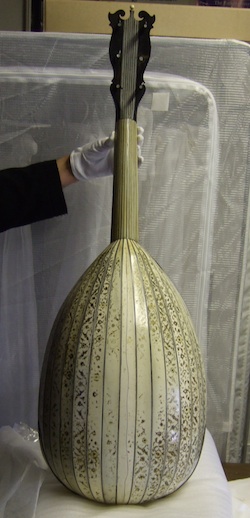
The Lacote Decacorde in St. Cecilia's Hall, Edinburgh

I continued my instrument museum holiday in Scotland by visiting St. Cecilia's Hall, Edinburgh to see examples of several guitars that have I been collecting information about; Lacôte's decacordes and guitars built by members of the Benedid family.

The two Lacôte decacodes that I examined recently in Paris differed from each other in various important details (my post of Feb 23). From published photos I knew that this guitar presented yet a third option for some of the same features.

The undated guitar (UEDIN:288) was built by José  Benedid in Cadiz sometime before he moved to Havana where he died in 1899. I thought this instrument could represent a point of reference for interpreting other guitars by the Benedid family that I intend to examine in the future. Since I want to describe both of these guitars in detail I'll write a separate  post for each.


A technical drawing of the Lacôte decacorde is available from the museum (UEDIN:767). I had a copy at hand while I studied the guitar and this saved me a lot of time in noting general details. The disposition of strings on Lacôte decacordes vary from 5 fretted and 5 open to 6 and 4 or 7 and 3. This example is arranged for 5 and 5. As listed on the drawing, the fretted string length is 630 mm while the open strings, set on a slanted nut, vary from 683 to 715 mm.
The book-matched soundboard is impressively close grain spruce that widens only a couple of centimeters from the edge to 1.5mm between grain lines. The sound hole rings and edge banding are in the typical Lacôte style, composed of multiple narrow strips of  alternating ivory and ebony. The bridge appears to be original as it is precisely shaped in the Lacôte style and size. Interestingly, the bridge pin holes are not equally spaced. This feature is certainly intentional. The first through fifth holes are 12 mm apart while the sixth is 11 mm from the fifth. There are 10 mm between each of the remaining holes. The Lacôte decacorde in Paris, E.986.5.1 which is also arranged in a string disposition of 5 and 5 has a similar spacing although the holes are not as accurately spaced.

The back is a single piece of mahogany veneer glued over a piece of close grain quartered spruce, probably utilizing a shaped form in its preparation that results in an arched back. Across the lower bout the crown is 4mm high while at the waist it is 3.5mm and across the upper bout it measures 3mm.

The side ribs appear to be solid mahogany. Shining my pen light through the sound hole I couldn't be sure because of the accumulated grime and discoloration. Had the side ribs been constructed with a layer of spruce I presume this feature would have been visible because the grain pattern of even dirty quartered spruce is recognizable.

The design and construction of the neck and peghead for a guitar with this many strings is a challenge and Lacôte's solution is elegant. Although only five strings on this example are fretted while the remaining five are played open all ten strings lie over the fingerboard. It is structurally necessary to support these strings but acoustically it isn't.  Modern ten strings guitars that have all strings fretted are built with full width necks where the neck stock, whether it is spanish cedar or mahogany, fully supports both structurally and acoustically, the width of the fingerboard with no attempt to reduce the mass of the neck.
 Lacôte recognized that this wasn't necessary and chose to reduce the mass of the neck stock and ease the burden on the player by cutting a channel into the bass side of the neck from the peghead joint to the heel. In each photo, part of the ebony fingerboard is visible at the bottom of the channel. The heel is fully formed and centered on the body while the peghead is attached with the usual long "V" joint. Looking closely at this construction you can see that the neck channel was carved with the fingerboard glued in place because the under-side of the fingerboard has been gouged out in the process of carving the channel.


A similar solution is found on the signed instrument, E.986.5.1. Here the channel was cut and finished before the fingerboard was glued in place allowing the maker to fully contour and delineate both the principal part of the neck and the bass side support. Both of these examples demonstrate an elegant solution to a tricky design problem.


 The simplest solution is found on the unsigned Paris instrument E.1044. Here the neck width is made no wider than necessary to accommodate five strings. The continuation of the neck stock material to form a support for the bass strings is completely omitted. What you see in its place is the bottom of the ebony fingerboard supported on the edge by a separate, narrow piece of sculpted ebony.

The heel end of this arrangement shows an equally simple  construction. In this example, however, the heel is off-set to the treble side of the body to maintain symmetry.


photo of E.986.5.1, Paris
An interesting feature of this guitar is the pitch-raising mechanism, an idea borrowed from the harp, that Lacôte patented for guitar. The Edinburgh guitar retains only one of its original three mechanisms so I am using my photo of E.986.5.1. The mechanism is a brass lever, operated from the underside of the peghead that swings across an open bass string pushing it down onto a secondary nut and raising the pitch of the string a half step. Each lever swings in both directions so the three can alter the pitch of all five bass strings, three at a time.


An explanation of the mechanism is much more complex than the mechanism itself: The small blackened lever at the top is integral with the brass cylinder as is the threaded screw at the bottom and the squared section just above the former. The cone shaped feature is a separate brass washer that slips in place when the mechanism is assembled. The mechanism fits into a hole in the peghead the same diameter as the narrowest part of the assembly. The collar under the small lever holds the assembly in place when it is inserted. The cone-shape washer fits over the brass cylinder and rests in a similarly shaped counter-sink in the back of the peghead. Below the washer the cylinder is squared in order to fit snuggly in the corresponding square hole in the larger bottom lever. This arrangement allows the bottom lever to rotate the entire mechanism when the wing nut (item on the left in the bottom photo) is loose and locks everything in place when it is tightened.


During my visit I was situated in a room adjacent to the hall where the instruments were exhibited. The museum was closed to the public that day so I was able to wander at leisure during my breaks from work.
I would like to thank curator Darryl Martin for his time in arranging my visit and for his generosity is sharing his knowledge of the museum's extensive guitar collection.

Edinburgh University Collection of Historical Musical Instruments

Checklist of Plucked Instruments


Tuesday, October 2, 2012

The Unverdorben Lute in Dean Castle Scotland

Sue and I were in Scotland last week combining holidays with my museum appointments. I am fascinated with the 16th century lute maker Marx Unverdorben and I have made the examination and documentation of his lutes a special project. Unverdorben lutes are seldom used as models by current builders even though he is represented by as many surviving lutes (9) as his more illustrious contemporaries; Hans Frei (12) and Laux Maler (8). Note: totals from Klaus Martius'  lute database

Dean Castle houses an interesting Unverdorben that prompted our visit to Scotland. I was doubly fortunate because when I arrived I was escorted up a narrow winding  stone stairway to the top of the tower where space had been  prepared for me among the museum's wardrobe storage. Where would there be a more atmospheric place to study a 16th century lute?

I spent the day measuring and making templates of the bowl. Some lute makers built elaborate contraptions for recording bowl contours, but faced with a trans-atlantic flight I wanted to find a simpler way. I used the same principle but substituted laminated card stock for templates that I had prepared in advance.These were supported in grooves cut in pine blocks that were positioned on a paper grid. Throughout the process I used the grid to record reference points.


I cut pointed strips of thinner card stock and positioned these at close intervals against the bowl and taped them in place. Alternating from one end to the other then to the center of the arch this apparatus stabilized itself allowing me to create an accurate contour of the bowl's axis. I was particularly careful at the neck joint and at the point where the ribs bend over the edge of the front block.

I followed the same procedure for creating cross-sections. Here I found it necessary to use two markers per rib, each placed so that the marker's edge aligned with the rib joint. Sometimes this procedure was complicated by mis-shapened or ribs that were poorly aligned.


After finishing each contour I traced the result on heavy paper. Besides the axis contour I made four cross-sections; one at the deepest point of the bowl, another at the front block, a third between these two points and a fourth at a point equal to the bridge position.


I had seen museum photos and read descriptions of the lute so I knew in advance there were features of the instrument that were either not original or suspect.
 Mike's Oud Forums . I finished the afternoon examining these.

I was interested in determining if the bowl retained its original contour because the outline of the belly appears too full for a lute of this era. Lute bowls are flexible and were often forced into a different shape and fitted with a new belly during later re-buildings . The rear view of the bowl also suggests a degree of forced distortion and the belly displays a dip of 6 mm  or more from the imaginary plane when I put a straight edge on it. Luthiers achieve this latter effect by either cutting down the edge ribs or pushing the edge ribs out to a wider contour. You can see in a previous photo that the ribs have not been cut down by any appreciable degree.


 Is the belly original? It is very fine grain wood, but the design of the inset rose and the style of the guitar type bridge makes me suspicious. The current rose and bridge could occupy and obscure the position of the originals. I will compare the positions of these with the information that I have gleaned from other Unverdorben lutes that I have examined and analyze the contours of the bowl further before I reach  a decision.


I have no doubt that the neck is original. Its dimensions agree with surviving original six course lutes and it has a characteristic "V" shape like that found on the lute by Georg Gerle.


A convincing feature is how the 19th century guitar peghead fits into the original recess of the lute pegbox. The angle at the end of the ivory neck is 9 degrees. A line representing the seat of the recess is visible too. The edge strip of ivory veneer would have continued across this area to the nut, but it has been replaced with ebony in order to blend with the guitar peghead.
Certainly you have noticed the design covering the ivory ribs. This is a floral motif painted in black and gold. It appears on the fingerboard and around a small part of the circumference of the rose and a small portion along the soundboard binding. It is worn in areas that were subject to abrasion. Painted ribs are unusual, perhaps for the very reason evident here, but decorated ribs are not. Interestingly, Unverdorben has indulged before as represented by his lute, formerly in the V&A.
Unverdorben Lute V&A 193-1882


I would like to thank Jason Sutcliffe, Museums Development Manager, for arranging and making my visit so enjoyable and especially for sharing his passion for Dean Castle so enthusiastically with Sue and me.

Dean Castle
Dean Castle Country Park


Monday, September 17, 2012

Jauch Baroque Lute - The Black Lute

My Jauch triple-nut lute is finished.

Jozef van Wissem, the Dutch lutenist/composer, for whom I have built lutes since the 90's has, with each new order, asked me to built him a black lute: I have always protested and declined.

But last fall Jozef was in Toronto and stopped by after his gig with a convincing argument. His duet partner, film director/guitarist, Jim Jarmusch is making a movie about a centuries long love affair of a lute playing vampire; Only Lovers Left Alive. Josef has a hand in the movie score.

Black lutes were popular in the 18th century. But they were painted black, "ebonized" rather than built with ribs of ebony and often using curly maple. I have had the opportunity to examine several ebonized lutes. This is a photo of a Thomas Edlinger lute in the collection of Harvard University, HUCP3279, that was obviously ebonized during a later conversion. Much of the black paint has flaked off revealing the original brown varnish.

I decided to mimic historical precedent. I applied a chicory tea stain to darken the curly maple ribs a little and then sealed the wood with a light coat of clear lacquer. Before ebonizing the lute I strung it up and played a little; letting it enjoy a few days in a brief historical niche.

To ebonize the bowl I built up the finish with subsequent coats of black lacquer, sanding lightly between each one. After the lacquer had hardened a few days I rubbed out the surface with 4000 MicroMesh and waxed with conservator's wax.

When I agreed to build the black lute Jozef was adamant that it needed to be all black. History has a way of repeating itself. While researching this lute I read an article by Eszter Fontana, The Case of the Missing Lute, JLSA XXXV (2002) and was astonished to read in a footnote (pg. 4) a description of a no longer extant J.C. Hoffmann lute: "Very beautifully crafted body, black lacquered resonating belly with triple rosette."

I stained the belly black with spirit stain and sealed it with several light coats of clear lacquer, rubbed out and waxed.


photo courtesy of Jozef van Wissem


Last Monday, Jozef appeared at Le Poisson Rouge, New York, with the Black Lute.

Wednesday, September 5, 2012

The Triple Nut Extension - Continued

Previously, when I made triple nut or swan-neck extensions I used a drill press to remove the excess material and then trued the edges and finished the bottom of the excavation with various chisels. Using the drill press for this process makes me nervous. There is the risk of something slipping and ruining my work and it is generally rough work. So this time I decided to do the entire procedure with chisels - one pegbox per day.
I laid out the boundaries of the smallest cavity (you can see several reference lines) and proceeded to partially  excavate a small area with various sizes of chisels. Working like this it becomes obvious how to proceed: truing the edges, then deepening the recess, lengthening it a little and then truing again. I found that the work went quickly and neatly.

Of course, this pegbox was the easiest to do. The middle one requires working under the over-hanging nut support. It is made even more difficult because of the limited space for the six peg holes. The last hole for this rank of strings goes far under the over-hang. Here I am using a "skew" chisel to reach the rear of the recess. Note that I am using a waste portion of the original block as a support. Later, this cut-off along with the others will go in the wood stove this winter.


The first pegbox is a little more complicated in that the treble side has several crooks and curves. I lay these out with generous side cheeks which provide strength and stability. Here I am using a front bent chisel to clear the bottom of the recess. I like to leave more than six millimeters of wood thickness  in the bottom of this pegbox for strength. I can achieve this even with the relatively low profile of the pegbox by drilling the holes off center and closer to the top edge by a millimeter and a half. Although I found this work pleasing I still felt I needed some aesthetic gratification. I reamed out several peg holes in the finished pegboxes and inserted temporary pegs to see what the final product would look like.

One feature of this design puts the chantrelle in its own recess. This allows the string a straight run over the nut and into the pegbox cheek at an angle that is far less likely to break it. I drill a pilot hole and enlarge and square the recess with small chisels.

This photo also demonstrates how I clamp any of the types of  extensions that I make. I tie two wound bass string of the same size in the appropriate holes in the bridge at one end and on pegs in the pegbox. When these strings are brought up to equal tension the extension is pulled back into the neck joint in proper alignment. Two spring clamps hold it firmly against the bottom of the neck.

The back of the extension that over-laps the neck can then be contoured. Visible in this photo is the skewed angle of the rear of the extension. I leave a little more room on the treble side for the player's thumb to comfortably grasp the first fret position.


Next time I'll show photos of the finished lute and describe a surprising historical varnishing process.


Monday, August 27, 2012

Making the Baroque Lute Triple Nut Extension


A lute with a triple nut extension offers the baroque musician several advantages. Firstly, the tonal difference between the stopped strings and the longest open basses is less pronounced because the length of the strings is increased by a smaller increment with the addition of the intermediate nut. There is also the practical aspect that string diameters may be duplicated from one echelon of strings to the next.

The triple nut extension that Andreas Jauch made for this lute (Copenhagen, No. 104A) is designed in such a way that the length of the strings, stopped by the second and third nuts, are in whole number ratios relative to each other and to the fretted length.The original string lengths  are: 105, 93 and 78 cm. Thus, 105/93 is 9:8 which is a major second and 105/78 is 4:3 which is a perfect fourth. These ratios are important for preserving harmonic relationships across the lute's compass. I wanted to retain them in my lute.


Earlier model is on top
I hadn't build this particular lute and extension before 
so I needed to design and make a template. I used a previous
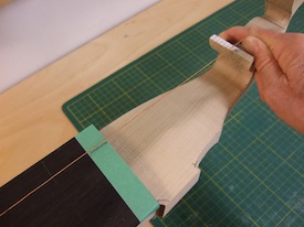
model as a guide. Since the proportions between nuts were different you can see that I shank the length of the first and second pegboxes. Since I was adding a fourteenth course I lengthened the third pegbox. Also, I wanted a more delicate look. The top template is 24mm thick at the first peg position. I reduced that to 20mm and diminished the remainder of the design accordingly. Because of the nature of the forces with off-set strings it is very difficult to anticipate how much the structure will bow up, twist side-ways, or otherwise move unpredictably, so there is always a concern for strength.

I decided I could accommodate this risk, first by altering 
some features of the design and second by using a freer approach to executing the design rather than following a template. I squared a block of poplar, laid out the template, band sawed the bottom surface. Here I am proceeding to finish the cuts on the top surface by using a drill press to fashion the tight contours in the design.


At this point I put the extension aside and cut the recess in the lute neck where the extension will sit finishing it with chisel and files. The third object on the bench is a strip of thin metal that I use as a guard to protect the adjacent wood surface when I'm working into a corner with the file. 

Once I'm finished with the joint I can check the alignment by clamping the extension to the neck. The intermediate nut carries the 9th - 11th courses and the third nut carries the 12th - 14th. I mark these string positions on the top of the nut arms. This procedure determines the way the two pegboxes are off-set to the bass side. Now I can layout the side contours.
I saved the waste portions of the original block of poplar and glued the whole assembly together with pieces of thin cardboard sandwiched in between the parts. Referring to photos of historical triple nut extensions I drew the side contours on the top of the re-assembled block allowing for some adjustment in  the final shaping. Then I band-sawed the design. I didn't have a photo of this stage but the following photo and description explains the same process.


Here I have tack glued the extension in place and am carefully checking the alignment again. The position of the 9th course as it crosses the nut is marked on the piece of painter's tape so I can run a string from the 9th course on the bridge over the position mark and check the alignment on the second nut. The part of the nut support to the treble side of the string is waste and will be cut off. The treatment of that is one of the design elements that has to be worked out. As I mentioned earlier, I had decided not to work from a predetermined plan but to allow the design to evolve.


This photo, while showing the alignment of the 11th course as it clears the intermediate nut, also shows the initial shape of the treble side of the extension. I have yet to cut the final contours.


The first thing to notice in this photo is the way I off-set the intermediate and third pegboxes. The bass side of the first pegbox is straight. The second is off-set with an edge that defines a "S" curve with the nut support. The second pegbox snakes toward the bass and terminates with the "S" curve of the  third pegbox.

To drill the peg holes I set the extension in a machinist's vise and supported the free end. The holes in the first pegbox are drilled perpendicular to the center line of the neck.
The second pegbox leans toward the bass and the third pegbox slants back toward the treble, creating a subtle crook. The holes in the third pegbox are drilled close to the perpendicular of its center line and the holes in the intermediate pegbox nearly follow the crook.
I drill from both sides of the extension with the intention that the holes will line-up. That is problematic, so I use a small drill bit. This allows some adjustment when enlarging the hole to peg size later on. I took great care and fortunately all of the holes lined up.


I made several attempts to fashion an agreeable contour on the treble side. The weak spot on the triple nut extension is at the end of the first pegbox where it narrows significantly and the torque from the intermediate and third nuts exert their force. When I initially band-sawed the side contours I left extra wood planning that I would need to experiment with the design. What I settled on is seen here. The end of the first pegbox is rounded smoothly with the side of the nut support tapering away gently. The pegbox ends in a slight crease, but then broadens out a little to begin the intermediate pegbox. This arrangement leaves a fair amount of wood and thereby avoids a design weakness. The intermediate pegbox thins only a little in width and depth and rounds quickly onto the flat surface of the third pegbox.

Next time I'll excavate the peg recesses, finish the area around the joint with the neck and glue it on.


Saturday, August 11, 2012

The Soundboard Barring for the Jauch Baroque Lute

In my last post I cambered the neck and glued on the 2mm thick ebony fingerboard. Now it was time move on to barring and fitting the soundboard. This is one of my favorite and most satisfying lute making activities. I spend a lot of time comparing barring patterns used by historical makers, reviewing what I have done before on similar lutes and thinking about the approach I want to take.

Ivo Magherini, who provided me with the drawing and photos for this lute, was also able to get a glimpse of the interior.


Ivo Magherini photo
Even though the original lute is intact there are several large cracks through which "it was possible to assess part of the barring layout," Ivo reported.
The first bar is 32mm in front of the bridge (measurements are taken from the middle of each bar). The second bar is 76mm from the first. The third bar is 59mm from the second. The fourth bar is 50mm from the third. This bar is the center of the rose.  There is one bar that runs from the curved edge of the belly to under the treble tip of the bridge. There was no trace of a J bar (bass bar) It was not possible to determine what the arrangement of bars was like in the area above the rose. For reference, the front of the bridge is 101mm from the rear of the belly.

 I think of the three bars between the bridge and the rose  as primary bars. Their placement and size control the strength and evenness of the tone. At 32 mm from the bridge the position of the first bar provides strength. The location of the second bar, unevenly spaced closer to the third than the first deserves comment. Friedemann Hellwig in his important article, On the Construction of the Lute Belly, Galpin Society Journal XXI, 1968, describes the division of the lute belly by 16th and 17th century lute makers into equal parts with the bridge and bars placed proportionally. I followed this method when I first started building but I had problems with overly assertive notes or weak ones. Eventually I attributed this to equal spacing and when I moved the second bar the tone evened out. Jauch placed his second bar more unequally than I would but I decided to follow his example - after all, these guys knew what they were doing.  The barring I used to support the triple rose area is not the only solution but one that is found in many lutes. Since my client for this lute plays with light tension strings I decided to use only two bars between top of the rose and the front block rather than three. Also, I always make this area of the soundboard thicker than elsewhere, around 2.0 - 2.1 mm. So I didn't think it needed extra support.
The barring pattern in the area around the bridge that I used is typical of Jauch's era. The size and exact placement of the individual bars is based on my experience. I alter dimensions and placement to fit the requirements of individual clients. I drew the diagram from the finished belly. I have made one for each of my lutes dating back to the mid 80s. The belly thickness is listed in 1/1000 inches. So "74", for example, is 74/1000 or about 1.9 mm. I'll continue with a short explanation  to help you decipher the diagram. The first finger bar on the treble side (right) measures 7.5mm high at  the hash mark and tapers in both directions to 0.0 under the tip of the bridge and 2.0mm where it glues to the rear of the bowl. It is 3.9mm wide. The first harmonic bar is 4.2mm wide and 15.8 high. The hash mark near the end denotes the beginning of the scallop. The bar as it glues to the rib is 6 mm high.
Throughout the process of shaping the bars - rounding the tops and cutting the scallops - I listen to tap tones. Not necessarily the pitch but the clarity and strength. It changes as the bars are shaped, changes again when the bridge is glued on and then again when the belly is glued to the bowl. I make adjustments to maintain the strength and clarity. I always string up my lutes before varnishing to see what  how it turned out. More than once I've opened a lute and moved a bar or added a "sweetener".

To finish this post here is a photo of the bridge. Because there is a fourteenth course the bridge is a little wider. To compensate,  I shortened the bridge tip.

Before gluing the belly on the bowl I was careful to make sure the bar ends fit snuggly against the edge ribs and by stretching a piece of sewing thread from the bridge to the nut I assured myself that the neck was in proper alignment.

Next time I'll describe making the triple nut extension.

Wednesday, July 25, 2012

The Baroque Lute Fingerboard

The hands-on technique of cambering the neck of baroque lutes doesn't lend itself to a photographic explanation. I only took a few photos while I was cambering the neck for the Jauch because it was difficult to see the details. But on one of my research trips I took photos of the fingerboard camber on two well known lutes:  Thomas Edlinger, No. 497, in Leipzig and the swan-neck lute by Sebastian Schelle, MI 46 in Nuremberg.


This is the nut end of the Schelle fingerboard. The curvature of both the nut and the ivory inlaid panel show the degree and evenness of the camber. I measured the height to be well over 4mm. The fingerboard is 78mm wide at this point.


The height of camber at the neck joint of MI 46 is over 2mm and exhibits the same evenness as at the nut. The neck width is 105mm.

These measurements are estimates because the rounded edges of the fingerboard do not allow exactness.


Here's a sample of two necks. The one underneath is the neck of the Jauch that I am building. I have cut out the recess for the triple nut extension and except for final smoothing of the fingerboard surface and rounding of the bass edge, it is finished. The one on top is from one of my theorbos. Unfortunately, the lute was left leaning upright in a corner and fell over, splitting the area of the neck at the back of the recess for the extension. Re-gluing this type of damage always leaves the joint weak, so I replaced the neck, but saved the artifact.

 I put a fairly high camber on the theorbo neck. This was requested by the client. But you will notice that it is unbalanced. The camber on the bass side flattens out a little which leaves the bass side of the neck thicker. This is intentional. There is no need to continue the same degree of camber on the bass side because the fretted strings stop 2/3 of the way across the neck as denoted by the recess for the nut. The extra wood on the bass side serves to strengthen the neck.
When I glue the neck in place its top surface is on the same plane as the top surface of the side ribs. In order to build a camber into the neck some makers glue a thin wood slab on top of the neck that is then shaped to the desired camber. But the higher the strings are above the plane of the lute, the more upward pull there is on the neck.


Photo: German National Museum, Nuremberg 


This is a restoration photo of the bare neck of the Sebastian Schelle, MI 46. The smudges are glue "shadows" of the inlaid ivory design left on the surface after the fingerboard was removed. On the right end of the neck you can see the recess for the nut and the curvature of the camber. In this example Schelle created the camber directly from the core wood rather than from an added slab. The advantage to this method is that those strings that lie farther from the neck center are closer to the plane of the lute. The top string at the nut, for example, actually lies below the plane. The second string may as well. On lutes with 11 courses on the fingerboard several of the lower courses may lie close to or below the plane of the lute. The over-all effect is to lessen the total upward pull on the neck.

The technique for cambering the fingerboard calls for patience and precision. Whatever the height of the camber is at the nut end of the fingerboard the camber must be continued, to some degree of curvature, the length of the neck and across the front block area. Otherwise, the top and bottom strings will lie very close to or on the neck.

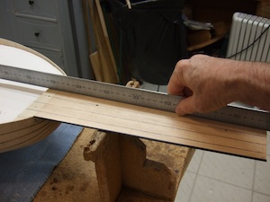
I secure the lute in a cradle and work from the front. Using a block plane with a fine setting I start cambering the neck from the nut area down the length of the neck, across the front block and on to the top edge of the side ribs. Progress is slow as I must check frequently for accuracy. Across the neck I use a straight-edge to eye-ball the camber. In the photo, in which I am beginning to glue the fingerboard in place, you can see four pencil lines on the neck wood. These represent the second, fourth, sixth and eighth courses. I use these as guides to determine the levelness along the axis of the neck (see previous photo). When I was confident the camber was accurate I bent a piece of 2mm thick ebony over a hot pipe and glued the fingerboard in three stages as was shown and described in an earlier post.

My clients are not unanimous about the degree of camber and I construct variations.  Historical lutes also exhibit a variety of cambers both at the nut and the neck joint.


The degree of camber at the nut on this lute by Thomas Edlinger, No. 497 in Leipzig is very much like the Schelle.


 But at the neck joint the camber has flattened, relatively more, than the Schelle and is only a millimeter or so high.


All photos by the author unless otherwise noted.