Friday, November 20, 2015

Building a Stauffer Terz Guitar- Part 2


In my last post I focused on constructing the adjustable neck and the corresponding V slot.  Now it is time to describe assembling the body of the guitar.


Since I had cut the V slot before I glued the front block onto the side ribs it was essential the everything remained properly aligned. With the side ribs clamped securely in the mold I then clamped the mold to the edge of my bench with the axis positioned on one of the lines on the mat. Then I glued the front and rear blocks in place.


The back slopes gently toward the waist and then plunges by nearly 15mm to the neck joint. The height of the side ribs are contoured from 77mm at the tail to 70.5mm at the waist and then to 56mm at the neck joint.


 This creates difficulty in bending the interior linings for the back because they must conform to both the outline of the guitar and the sloping profile of the sides as well as fitting snuggly against the inside of the ribs. When the profile is less drastic the linings can be bent and twisted into the proper shape. But here that is not possible. I solve the problem by making my lining material extra deep, bending it to the contour and clamping it to the ribs, letting the extra width overhang. Scribing a line, as shown, denotes the correct profile. A second line scribed parallel to the first and then removing the excess makes the linings uniform in depth.  


Once the linings are cleaned up I complete the frame by shaping and fitting the struts for the top and back. These all follow the size, shape  and placement given on the museum's drawing - with one exception. I added a smaller strut, thinner and lower,  in a position behind the bridge.  I like to assemble the backs and tops in this manner. The ends of the struts fit perfectly into notches in the linings, and as a result, the frame is perfectly stable and remains so when the top and back are glued in place. The three back struts are arched as much as 4mm for the lower bout and nearly 3mm for the upper.


The two lower struts on the top are arched 3mm while the two above the rose are flat. These values are my choices.  I also include a thin maple bridge plate that conforms to the arch of the top. The museum's drawing has no information about arching, nor is a bridge plate part of the original guitar.

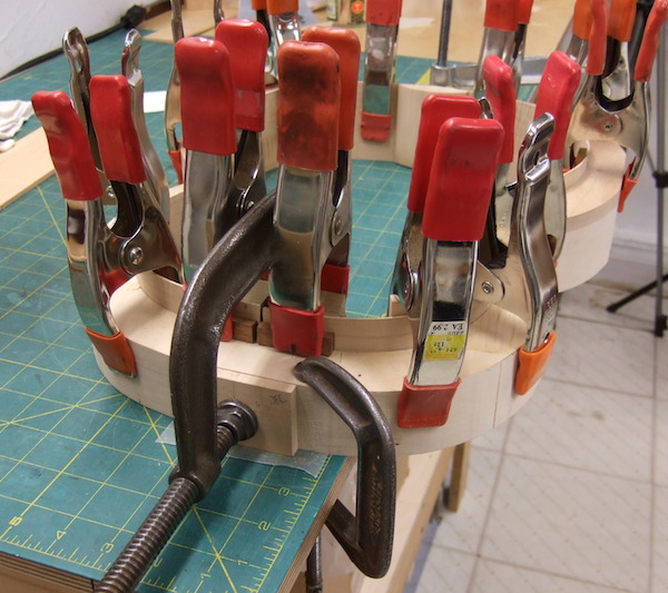
I describe my technique for gluing the back and top onto the struts and frame in  "older posts" from 1/20/13, 9/19/11 and 9/10/11.


The original Stauffer soundboard is thin. The area from the bridge through the sound hole and up to near the front block is 2.1 - 2.2mm. Other areas are 1.9 - 1.7mm. I used the same sort of gradation but I started at 2.4mm.

J.G.Stauffer MIM 4152, Berlin


 The museum plans do not include details of the purfling or the design of the bridge. I photographed the guitar but only in its location in a free-standing display case. The photo is of little value because of poor light and reflections.


N.G. Ries, private owner


I do have a Nicolaus Georg Ries guitar circa 1840 in my shop.  I consulted it for the design and details of the bridge, purfling, peghead and neck contour.


The Ries purfling design is similar to that found on many of Stauffer's instruments so I chose a variation of that for my terz.


Because the waist is so tight I didn't trust the strength of the my masking tape to hold the multiple strips in place at the waist. Also, I chose   not to glue on the thicker hardwood outer piece  at the same time as the others. I substituted a plastic strip and glued everything in the normal way. A special purpose caul with a large cam clamp that spanned the waist secured a tight fit. Hide glue doesn't stick to plastic so the next day I peeled the strip off and glued  on the final ebony strip.


The Ries bridge (see previous photo) is a delicate design that was often used by the Viennese builders. The original is made with a hardwood painted black. I photographed the Ries bridge, re-sized it to the dimensions I needed, printed it and from that made a simple template. I chose a piece of European plum, drilled the bridge pin holes and cut the saddle fret slot.


Here's the finished piece ready to be blackened.
Viennese bridges are usually very low. This one is 5mm high, tapering to less than 2mm at the ends. The rear slopes to about 2.5mm.


Next time, I'll post a photo album of my finished guitar with further descriptions and explanations.

All photos by the author.


Tuesday, November 3, 2015

Building a StaufferTerz guitar


I recently finished a model of Johann Georg Stauffer's terz guitar  Cat. No. 4152 in the Berlin Musical Instrument Museum. This guitar was on display when I was in the museum examining their Christoph Koch theorbo several years ago and that piqued my interest.

Many of my lute/baroque guitar clients play 19th century guitar and I have tried to finish one or two guitars a year for the last twenty years. Recently I have been able to spend more time with them; either by scheduling museum visits, doing restorations and repairs and other opportunities. These occasions are recorded in my 'Older Posts'.

A technical drawing for this instrument is available from the museum.
http://www.sim.spk-berlin.de/en/drawings_570.html

The guitar's dimensions:
string length 554mm
body length 390mm
upper bout 228mm
waist 161mm
lower hour 290mm
maximum rib depth (tail) 77mm, minimum (neck block) 56mm


I built an inside mold  and immediately set about assembling the side ribs. The model has a very tight waist and I was extra careful while making this bend. I made the side ribs about 1.7mm thick over-all but thinned out the waist area to 1.4mm. I wear heavy deer-skin gloves while I bend guitar  ribs. The gloves enable me to cup my hands over the wood and to hold it firmly on the hot iron. In this way I can feel the wood fibers soften and gauge the amount of pressure I can safely apply. I clamped the bent side ribs securely in the mold and set it aside.


The guitar has a raised fingerboard that rides above the soundboard.  The heel of the neck sits in a deep V shaped slot cut into the front block. A simple screw mechanism allows the neck angle to be adjusted with a clock key. It is an ingenious device that was an important  and popular feature of nineteenth century Viennese guitars.


The mechanism is simple in principle but constructing it needs to be done accurately in order for it to operate smoothly. I find it easier to achieve this if I rough out the front block and neck/heel right after the ribs are assembled. This photo show the rear of the block with part of the mechanism in place. The guitar is upside down and you can see the bottom of the slot in the front of the block.


Here is the slot shown in the finished guitar. A wood dowel (shown in both photos)  protrudes through the centre of the upper part of the block. This fits into a blind hole (visible in the next photo) in the rear of the heel.


The dark area is discoloration


The dowel and the surrounding area acts as the fulcrum for the neck to pivot. It also keeps the neck from shifting out of position. The area beneath this is cut back in such a way that only the upper most area is in contact with the rear of the slot. Since the neck pivots on this point the hole must be slightly larger that the dowel.


Here is the mechanism laid out and partially assembled.

From the left, the anchor is the square plate attached to a hollow cylinder that is threaded inside and out. The square part is visible in one of the above photos. It is inlaid into the rear of the block. This keeps it from turning when the mechanism is adjusted. The washer is threaded and securely locks (as shown above) this part of the mechanism in the front block. The hexagon shaped cylinder is open at the front as seen in the photo below, but closed at its rear, except for a hole that allows the adjustment rod to pass through.


The rod passes through the heel. It is threaded at the rear end so that it screws into the rear cylinder. At the front it has a collar (above photo) that holds the rod in the front cylinder. The clock key fits the squared end of the rod.  A quarter turn in direction or the other will change the pitch of the neck raising or lowering the height of the strings above the fingerboard.


This has been a wordy description but here's one last photo that shows the roughed-out nature of the neck. The heel is a separate block glued to the neck. The sides of the heel are cut and planed to the contour that matches the V slot. At the rear part, the heel is cut away leaving a ledge. This is the location of the dowel and the point where the neck pivots in the slot.


And here is the entire neck showing all of the details of its construction. The peg head is attached with a v-joint. The extension that supports the flying fingerboard is attached with a half-lap joint and then tapered to achieve the characteristic Viennese fingerboard.


In the next post on this guitar I'll describe constructing the soundboard, back and bridge and my procedure for polishing the guitar.


All photos by the author.